When you click on links to various merchants on this site and make a purchase, this can result in this site earning a commission. Affiliate programs and affiliations include, but are not limited to, the eBay Partner Network.
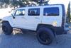
Hummer H3For the Hummer driver who wants the rugged look and off road capabilities of the Hummer, but in a smaller size and with a more fuel economy friendly engine.
The upper control arm was straightforward. The entire arm was replaced. I did that one some months ago along with shocks.
The lower control arm was rebuild-able. Bushings and ball joints available. The rear lower bushing is in the frame even if you were purchase a complete lower control arm. Even after searching the interwebs, this left me with some head scratching. I thought I'd share what I did...
Some odd tools involved
Balljoint press
Impact wrench
Sawzall
4 -1/2" electric grinder
3" air grinder
Air hammer/chisel
Drill
Pliers
Torsion bar has to come out. After lifting the vehicle and counting the turns to remove the adjustment bolt, the drivers side pulled right out. The passenger side followed the more expected process of an hour of wiggling, pulling and swearing. I did not have to drop gas tank or anything like that on my H3T to get the bars out. There is a bolt in front of (underneath) the torsion bar (21mm? socket) making up the rear pivot.
Separate upper ball joint, remove and hang caliper, remove rotor, axle shaft, tie rod end...sway bar links. The OEM sway bar link studs have a round shoulder. They just spun away under the impact gun despite best efforts with a pair of pliers. The allen wrench hole in the end of the stud rather useless at this point in the vehicles life. I cut them off with a grinder. The Moog replacements I purchased (project delay #1) have flats on the stud for a wrench. They will be reusable.
I disconnected the wheel speed sensor just behind the inner fender. Popped the connector off its mouning clip, pried the two shock tower clips out and pulled the wire from the guides on the upper control arm. I then finished removing the steering knuckle from the truck.
On the driver side, the front lower control arm bolt was seized in the bushing. I had to lay a sawzall in and cut through the bolt on between the frame and control arm each side to get the front pivot out. The rear pivot bolt that was in front of the torsion bar came right out on both sides.
I did not drop the front axle to get the frame bushing out. I did remove the axle support brackets to get some more room. With the axles out and brackets off, replacing the inexpensive axle seal was a no-brainer.
Before starting, take note of the gap between the bushing flange and the frame. The bushing is not fully seated. I could barely get my balljoint press around this bushing as someone else had suggested. Maybe theirs is bigger?
I might have budged the bushing with my press, but it wasn't coming out. I drilled the rubber around the center sleeve using a large enough bit that it scored the inner and outer sleeve. With 8-10 holes all the way through the rubber perimeter, I was able to dislodge it with some hammer blows and twist it out with large pliers. Then the rubber pulled out of the outer shell. I notched the bushing flange with my smaller air grinder to give it room to collapse. Using the air chisel, the outer shell was collapsed enough finally tap it out with a hammer.
Installation of the new one was completed using the balljoint press directly on the flanged end of the bushing. No driving spacers or blocks. Do not seat the bushing all the way into the frame. The gap isn't so critical, but there needs to be about 4-6mm.
The balljoint R&R was no issue. Removing the bushing from the control arm was simple enough. I used the balljoint press with the plunger directly on the center bolt sleeve. My balljoint receiving cup was not deep enough to do it in one shot however. I had cut off what was sticking out with my electric 4-1/2" grinder and reset the balljoint press to push the rest out.
I could not figure out how to get this double flanged bushing into the control arm.
Eventually, I decided to set-up on it with the ball joint press and just give it a shove. It went way cockeyed and I reset to try and keep it straight. It went crooked again, this time I just kept pushing and it went in.
It all went back together without much drama. I jacked the lower control arm up to ride height eyeballing the axle shaft angle before torquing the two pivot bolts. There was a lot of cleaning and painting. Wire wheels and rust dissolver. Brake pads were worn which was odd so I ordered new (delay #2). I didn't think they were that old. Turns out both calipers had at least one stuck piston; that's why (delay #3).
The inner and outer tie rods were also replaced. 1-3/8 open end wrench to remove the inner. The wrench wouldn't fully seat on the Moog replacement inner. A 36mm or 1-7/16 might have been a better size. I read some warnings about typical inner tie rod tools not being big enough, so I didn't even try renting a set. Re-using the tie rod boot the small end was stretched out. I added some RTV into the notch to improve the sealing.
I hope the new owner appreciates all this work. Shortly after starting this project, my wife found an H2 SUT she had to have. Of course the front end of that one is all kinds of messed up as well. I don't think we are going to keep two Hummer trucks.
Could you put the part numbers you used? I'm having trouble finding the frame bushing.
Never used the internet? Google "H3 Hummer control arm bushing"..... crazy how that works. Much faster than digging up TWO YEAR + OLD Threads to tack on a question.

 08-24-2019, 11:50 AM